













10 Technical Interview Questions for Mechanical Engineering
Updated September 16, 2026
23 min read
Interview Pilot Editorial Team
You're at a whiteboard, and the interviewer has given you a mechanical component, an applied load, and incomplete information. They're not only waiting for the final number. They're watching whether you clarify the objective, sketch the system, state reasonable assumptions, identify the governing laws, work through the math, check whether the result is physically plausible, and connect it to a design decision.
That pattern is the foundation for strong answers to technical interview questions for mechanical engineering. University engineering career resources describe interviews that combine technical fundamentals with project challenges, design tradeoffs, pressure handling, and communication, rather than testing credentials alone. UC Davis Engineering's interview guidance reflects that blend, while Wisconsin Engineering Career Services' question guidance emphasizes behavioral judgment alongside technical discussion.
The ten questions below move from mechanics and thermal sciences to simulation, manufacturing, controls, and troubleshooting. Each one is presented as an interview performance: what to clarify, which principles to use, how to reason aloud, and what follow-up question may come next.
1. Stress-Strain Analysis and Material Properties
Question: A structural member experiences an axial load. How would you determine whether the material remains safe?
Start by clarifying the load, cross-sectional area, material, temperature, and whether the force is steady or cyclic. For a simple axial case, calculate normal stress with ( \sigma = F/A ). If the material behaves elastically, use Hooke's law, ( \sigma = E\epsilon ), to relate stress to strain. Then compare the calculated stress with the relevant allowable value, not automatically with ultimate strength.
Say your assumptions aloud: the load is concentric, the section is uniform, local stress concentrations are absent from the first estimate, and the material properties apply at the operating temperature. That signals that you understand the difference between a simplified model and a production design.
How to turn the curve into a decision
Explain the stress-strain curve in sequence. The initial linear region represents elastic behavior. Remove the load there, and the component returns approximately to its original shape. Beyond yielding, plastic deformation begins, and the part may not recover fully. Continue by distinguishing yield strength, ultimate strength, and fracture, then explain why a design may need a margin against yielding, fatigue, or instability.
For an aircraft fuselage panel, for example, cabin pressure creates repeated loading rather than one isolated event. For an automotive suspension part, strength, stiffness, corrosion, mass, manufacturability, and cost may all affect material selection. Material selection for end-use parts can support that broader design perspective.
Practical rule: Don't stop at “the stress is below yield.” Explain what the result means for deformation, durability, inspection, and the chosen manufacturing process.
A useful rehearsal tool is the Interview Pilot question bank, where you can practice stating assumptions before reaching for equations. Expect a follow-up such as, “What changes if the load is cyclic?” Move immediately to fatigue, stress concentration, surface condition, mean stress, and the need for testing or a more detailed analysis.
2. Thermodynamic Cycles and Energy Conversion
Question: How would you compare the performance of an engine, turbine, or refrigeration cycle?
First define the device and the performance measure. An engine may be judged by thermal efficiency, a turbine by work output and efficiency, and a refrigerator by coefficient of performance. Without that clarification, quoting a formula can produce a technically correct answer to the wrong problem.
Draw the cycle on a pressure-volume or temperature-entropy diagram. Identify where heat enters, where work leaves, and which processes are idealizations. Then apply the first law to track energy and the second law to discuss irreversibility. For a control volume, account for mass flow, enthalpy changes, heat transfer, shaft work, and kinetic or potential energy when they matter.
A spoken worked-answer structure
Suppose the interviewer asks why a real Rankine cycle performs below its ideal version. State that the ideal cycle assumes simplified pump compression, boiler heat addition, turbine expansion, and condenser heat rejection. In practice, pressure losses, non-isentropic turbine and pump behavior, moisture during expansion, heat leakage, and finite temperature differences reduce performance.
For an Otto or diesel engine discussion, connect the diagram to the physical machine. Compression raises the working fluid's temperature and pressure, combustion adds energy, expansion produces work, and exhaust rejects remaining energy. Don't claim that raising compression always solves the problem. Discuss knock limits, component temperatures, combustion behavior, and the operating envelope.
If the question shifts to refrigeration, distinguish efficiency language carefully. A refrigeration system moves heat from a colder region to a warmer one, so work input is required. Walk through compression, condensation, expansion, and evaporation, then identify where pressure and temperature change.
Practice translating diagrams into plain speech with Interview Pilot's interview preparation tools, but keep the physics in your own words. A likely follow-up is, “How would you improve the cycle?” Answer with a tradeoff, such as improved heat recovery or reduced pressure loss, followed by the effect on complexity, reliability, controls, and maintenance.
3. Finite Element Analysis and Computational Methods
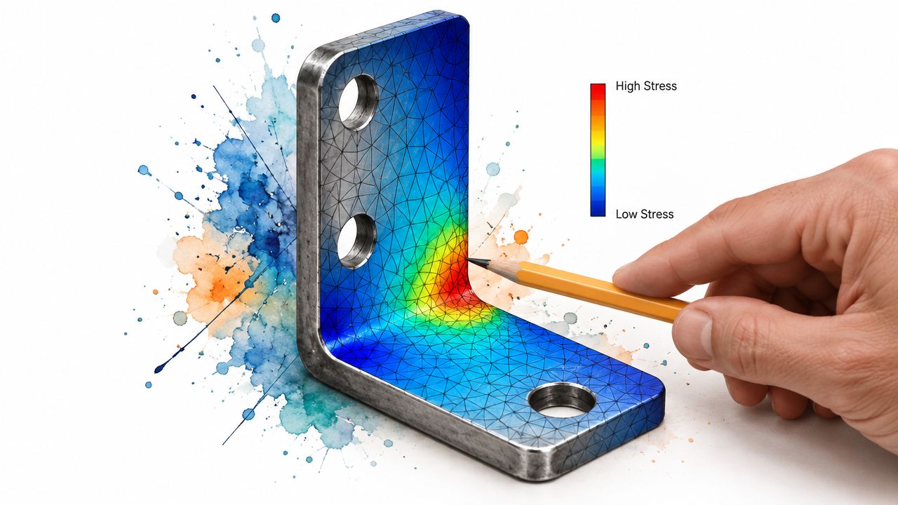
Question: You've received an FEA result showing a high stress region. How do you decide whether it represents a real design problem?
Begin with the physical question, not the software. Are you evaluating static strength, stiffness, buckling, fatigue, heat transfer, or vibration? Define the load cases and intended failure criteria before opening ANSYS, Abaqus, or COMSOL.
Next, describe the model setup. Simplify geometry only when the omitted features don't affect the result. Apply boundary conditions that represent the load path, avoid artificial restraints, assign credible material properties, and select a mesh that can resolve stress gradients. A refined mesh near a fillet or hole may be appropriate, but refinement alone doesn't correct an unrealistic constraint.
Separate numerical confidence from physical confidence
Explain convergence in practical terms. Increase mesh quality or density, monitor the quantity that drives the decision, and determine whether the result stabilizes. Then compare the model with hand calculations, an established analytical solution, or a physical test. If the result changes dramatically with the mesh, the model isn't ready to support a design decision.
The most credible answer includes limitations. A linear elastic static model won't capture plasticity, contact changes, large deformation, manufacturing residual stress, or fatigue unless those effects are represented. A thermal model may also depend heavily on uncertain convection coefficients and interface resistance.
“A simulation is evidence, not a substitute for defining the real system.”
After presenting the result, connect it to action. Would you change the fillet, thickness, material, support condition, or load case? Would you instrument a prototype? Would you run a nonlinear or transient analysis? Independent mechanical aptitude assessment guidance shows that screening can include CAD, FEA, mechanical design, quality control, spatial visualization, and tool recognition, so be ready to discuss both setup and interpretation.
Use the accompanying FEA walkthrough video only as a visual study aid, then rehearse explaining your own model without hiding behind software terminology.
4. Mechanical Design and Failure Analysis
Question: A component has failed in service. How would you identify the cause and redesign it?
Don't jump straight to a stronger material. First preserve evidence, document the fracture location and operating conditions, and ask what changed before the failure. Establish the load history, temperature, environment, assembly condition, lubrication, manufacturing process, and inspection record.
Then map possible failure modes. Yielding suggests excessive stress or inadequate section strength. Fatigue points toward cyclic loading, a crack initiation site, surface condition, or stress concentration. Buckling depends on compression, geometry, slenderness, and boundary conditions. Wear, corrosion, creep, and joint loosening require different evidence and countermeasures.
Build the diagnosis from load path to prevention
For a shaft that cracked near a shoulder, sketch the torque and bending path. Estimate nominal stress, identify the geometric stress concentration, and determine whether the crack orientation fits the loading. Examine the fracture surface if available, then compare the observed pattern with the predicted mechanism. Your answer should distinguish a hypothesis from a confirmed root cause.
After diagnosis, propose several redesign paths. Increase section size, improve the transition radius, change surface treatment, reduce alternating load, improve alignment, revise heat treatment, or modify inspection. Each option creates tradeoffs in mass, manufacturability, cost, and serviceability.
A design factor of safety belongs in the discussion, but it isn't a universal cure. Explain what uncertainty it covers and whether the governing risk is static strength, fatigue, buckling, fracture, or a combination. For a pressure vessel, reference the applicable design code and explain that code compliance, analysis, manufacturing quality, and inspection work together.
Use the fatigue-crack visual to practice describing evidence without overclaiming. A strong follow-up response to “How do you prevent recurrence?” includes a corrective design change, a process control, a validation test, and a way to confirm that the fix addresses the mechanism rather than only the symptom.
5. Fluid Mechanics and Flow Analysis
Question: Flow through a pipe is weaker than expected. How would you investigate the pressure loss?
Begin with the fluid, target flow rate, pipe diameter and length, elevation changes, temperature, and whether conditions are steady. Sketch the pump, valves, fittings, branches, and outlets. This control-volume view separates distributed friction along the pipe from local losses at entrances, exits, bends, valves, contractions, and expansions.
Apply continuity to relate flow area and velocity. Then write the energy equation, including pressure, elevation, velocity, pump head, and losses. Calculate Reynolds number to classify the flow as laminar or turbulent, then choose a suitable friction-factor method. State the source of each fitting coefficient rather than inserting unexplained values.
Connect the equations to the hardware
A reduced diameter raises velocity if mass flow remains constant. The associated kinetic-energy increase can lower static pressure, while friction and fittings remove mechanical energy from the flow. Compare the resulting pressure with the fluid's vapor-pressure limit. A low pressure near a pump inlet or restriction may indicate cavitation risk, so inspect suction conditions and local losses.
Use the application to decide which result matters most. In an HVAC duct, balanced airflow across branches may matter more than maximum flow. For an aircraft wing, pressure distribution, separation, lift, and drag govern performance. In a chemical pipeline, viscosity, fluid compatibility, temperature, erosion, and control-valve behavior may control the design.
Check the result twice: Confirm units, then ask whether the predicted velocity, pressure, and pump requirement are physically plausible.
A clear spoken response is: “I'll define the control volume, state whether the fluid is incompressible, apply continuity, write the energy balance, estimate pipe and fitting losses, and compare the pressure with operating limits.” Expect follow-up questions about compressible flow, pump selection, or how diameter changes affect energy loss and capital cost. Dawid Kowalski's Mechanical engineering interview guidance from Indeed also covers practical subjects such as hydraulics and piping and instrumentation diagrams.
6. Control Systems and Dynamic Response
Question: A motor-driven mechanism overshoots its position and oscillates. How would you improve the response?
Start by defining the input, output, sensors, actuator, mechanical load, and acceptable response. Draw the feedback loop. Identify inertia, damping, stiffness, friction, delay, saturation, and any disturbance that could produce the observed behavior.
For a simple rotational system, write the torque balance. The motor torque accelerates inertia, while damping and load torque resist motion. Convert the model into a transfer function if that representation helps, then explain what the poles imply about stability and response. Don't recite “increase proportional gain” without describing the consequence.
Explain controller changes as tradeoffs
A proportional term can reduce position error but may increase overshoot or excite unmodeled dynamics. Integral action removes steady-state error, but it can accumulate during actuator saturation and worsen recovery. Derivative action can add damping, though measurement noise may become a problem. A practical answer mentions filtering, anti-windup, actuator limits, and sensor quality.
For a robotic arm, connect tuning to trajectory accuracy, payload variation, gearbox compliance, and collision safety. For manufacturing equipment, consider cycle time, repeatability, vibration, and fault behavior. Validate the controller in simulation, then test gradually with safe limits and logged data.
A likely follow-up is, “How would you know the system is stable?” Discuss pole locations, time response, gain and phase margins, or a Bode plot, depending on the interviewer's preferred method. Explain rise time, overshoot, and settling time in words before using them as metrics.
Candidates preparing across disciplines can also review technical interview questions for electrical engineering, particularly where control, sensing, and electromechanical systems overlap. Your answer should end with the design implication: the best controller isn't merely fast. It remains stable and stays effective when the mechanism differs from the model.
7. Vibration Analysis and Modal Behavior
Question: A rotating machine has developed a strong vibration at operating speed. What would you check first?
Ask when the vibration appeared, whether it changes with speed or load, which direction it occurs in, and whether it is present at the bearings, housing, shaft, or connected structure. Review recent maintenance, alignment work, balance changes, mounting changes, and process conditions.
For a simple mass-spring system, the natural frequency follows from stiffness and mass. Damping controls how sharply the system responds near resonance. If the forcing frequency approaches a natural frequency, vibration amplitude can rise sharply, so changing stiffness, mass, damping, operating speed, or isolation may solve the problem.
Use frequency as evidence
A spectrum can help distinguish likely causes. A dominant component associated with rotational speed may suggest imbalance. Components linked to alignment, looseness, bearing defects, or gear mesh require different investigation. Don't diagnose from one spectrum alone. Compare directions, phases, operating states, and historical trends.
For turbine blades or a vehicle suspension, modal analysis helps predict how the structure responds to excitation. The model still needs credible boundary conditions and mass properties. Test data can reveal modes that a simplified model missed.
Describe a controlled diagnostic plan. Verify sensor placement and calibration, collect baseline data, inspect fasteners and couplings, check balance and alignment, then test one change at a time. If the vibration indicates a resonance, don't add material. Determine whether the added mass shifts the mode in the desired direction and whether the new design introduces fatigue or support problems.
See this guide to preventing equipment failure with modal analysis for a practical connection between modal behavior and reliability. Finish with the safety implication: if vibration can cause fatigue, loosened joints, seal damage, or loss of precision, define an operating limit and verify the corrective action under representative conditions.
8. Manufacturing Processes and Design for Manufacturing
Question: You need a functional metal bracket quickly. Would you machine, cast, form, weld, or additively manufacture it?
Clarify the part's geometry, material, quantity, tolerance, surface finish, load, lead time, and available equipment. A simple sheet profile may favor laser cutting and bending. A complex prototype with machined interfaces may need CNC machining. Casting can suit repeated shapes, but tooling and post-processing affect the decision. Additive manufacturing may help with complex geometry, though anisotropy, surface finish, support removal, and inspection must be considered.
Show that the drawing is a manufacturing decision
Start with the functional interfaces. Decide which surfaces need tight control and which can use looser tolerances. Add datums that reflect how the part will be located and inspected. Avoid unnecessary precision because it can restrict process choice and increase inspection effort. Check wall thickness, tool access, bend radii, corner radii, draft, weld access, and assembly sequence.
For an injection-molded plastic housing, consider draft, uniform wall thickness, ribs, sink marks, parting lines, and ejection. For a machined aluminum component, consider setups, tool reach, chip evacuation, and whether a deep pocket creates avoidable cost or distortion. For a welded frame, consider distortion, fixturing, access, and weld inspection.
A manufacturable design makes the intended process obvious. If the drawing requires the factory to guess, the design isn't finished.
Use design-for-manufacturability rules as a prompt for your review, then explain your decision as a tradeoff rather than a preference. A good answer might say, “I'd choose the process that meets the critical interfaces and load requirements with the fewest operations, then validate the prototype before committing to a higher-volume process.”
Expect follow-ups on tolerance stack-up, quality control, automation, and how design changes affect inspection. Current hiring guidance also points to manufacturing constraints, design revision, and root-cause thinking as recurring themes in structured engineering interviews. Apollo Technical's engineering question guide provides examples involving manufacturing constraints, fatigue, and failure-mode analysis.
9. Heat Transfer and Thermal Management
Question: An electronic enclosure is overheating. How would you reduce its temperature?
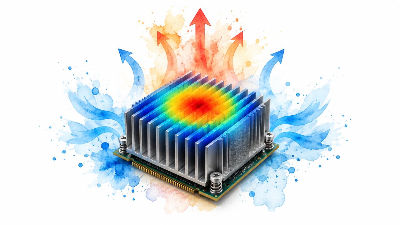
Start with the symptom and operating condition. Define heat generation, allowable component temperature, ambient temperature, enclosure orientation, airflow, and duty cycle. Then map the heat path from the source to the surroundings. Heat can move by conduction into a spreader or housing, convection from surfaces into air or liquid, and radiation to nearby surfaces.
For a first estimate, represent that path as a thermal-resistance network. Temperature rise depends on heat flow and total resistance, so compare each resistance to find the limiting bottleneck. The interface, conduction path, convection surface, or environment may control the result. For a changing load, include thermal capacitance and estimate how quickly the enclosure heats and cools.
Choose the remedy from the bottleneck
If conduction controls temperature, improve contact, reduce interface resistance, select a suitable thermal material, or redesign the heat spreader. If convection controls it, increase effective area, improve airflow, change the fan or duct, or consider liquid cooling. If radiation contributes meaningfully, examine surface properties and the enclosure's surroundings. In a building, insulation may reduce heat transfer. In an engine, coolant flow, material temperature limits, and heat-exchanger capacity must work together.
State the assumptions behind every correlation. Convection depends on geometry, fluid properties, flow regime, and boundary conditions. A correlation developed for one orientation or airflow pattern may not represent another.
Validate the model with thermocouples, resistance temperature detectors, infrared measurement where appropriate, or instrumented testing. Compare measured and predicted temperatures, then investigate discrepancies instead of adjusting the model to match one measurement.
A strong interview answer ends with the design implication: “I'd choose the smallest design change that lowers the limiting thermal resistance while preserving reliability, manufacturability, and service access.”
10. Mechanical Systems Integration and Troubleshooting
Question: A hydraulic or rotating system no longer meets its performance target. How would you find the root cause?
Begin with the symptom, not a favorite theory. Define what changed, when it changed, under which operating conditions, and how the performance was measured. Confirm the instrument first. A bad sensor, incorrect calibration, or changed test setup can imitate a mechanical failure.
Create a system diagram and trace the energy or force path. For a hydraulic system, inspect the reservoir, pump, filters, valves, hoses, actuators, and return path. For rotating machinery, map the motor, coupling, shaft, bearings, seals, supports, and driven equipment. Then compare expected behavior with measured pressure, flow, speed, temperature, vibration, and position.
Eliminate causes in a controlled order
Separate possible causes into mechanical, fluid, thermal, electrical, controls, manufacturing, and human factors. Rank them by evidence and consequence. Check simple, high-probability causes first, but don't ignore a low-probability failure with severe safety implications.
Use targeted tests. Isolate components, swap in a known-good part, change one operating condition, inspect filters and fluid, verify alignment, and compare signals at multiple points. Record the result of each test so the team can distinguish correlation from causation.
After finding the cause, define containment, correction, and prevention. A replacement bearing may restore operation, but the permanent fix might require alignment control, lubrication changes, a revised tolerance, a vibration limit, or a design update. Document what you learned and update the inspection or test plan.
This systems perspective matters because modern mechanical roles increasingly overlap with automation and digital tools. CECIMO's 2025 engineering skills report links significant mechanical and industrial engineering shortages with the adoption of automation and AI, reinforcing the value of engineers who can connect physical design with data-driven manufacturing.
For structured rehearsal, try an AI mock interview session. Practice defending each diagnostic step, including what result would make you abandon your leading hypothesis.
10-Topic Mechanical Engineering Interview Comparison
| Topic | Implementation Complexity 🔄 | Resource Requirements ⚡ | Expected Outcomes 📊⭐ | Ideal Use Cases 💡 | Key Advantages ⭐ |
|---|---|---|---|---|---|
| Stress-Strain Analysis and Material Properties | Moderate, conceptual + graphs; requires visualization 🔄 | Low–Medium, textbooks, material databases, simple test data ⚡ | Solid assessment of material behavior; identifies failure-mode understanding 📊⭐⭐ | Material selection, structural design, failure prevention 💡 | Tests foundational material science and practical design choices ⭐ |
| Thermodynamic Cycles and Energy Conversion | High, thermodynamic math and diagram interpretation 🔄 | Medium, calculators, cycle tables, T‑S/P‑V diagrams ⚡ | Evaluates efficiency reasoning and law application; theoretical vs practical limits 📊⭐⭐ | Engines, power plants, refrigeration, efficiency studies 💡 | Probes deep thermodynamics and system-level tradeoffs ⭐ |
| Finite Element Analysis (FEA) and Computational Methods | High, meshing, boundary conditions, convergence studies 🔄 | High, commercial/academic FEA software, compute resources ⚡ | Demonstrates practical simulation skills and validation capability 📊⭐⭐⭐ | Structural/thermal analysis, fatigue prediction, complex geometries 💡 | Directly reflects industry tools and modern workflows; actionable results ⭐ |
| Mechanical Design and Failure Analysis | Medium–High, code knowledge, trade-off reasoning 🔄 | Medium, standards, testing references, prototyping ⚡ | Shows design judgment, safety margins, and manufacturability awareness 📊⭐⭐⭐ | Component design, safety‑critical systems, lifecycle reliability 💡 | Balances cost, performance, and reliability; standards-driven answers ⭐ |
| Fluid Mechanics and Flow Analysis | High, PDEs, turbulence, empirical models 🔄 | Medium–High, CFD tools, experimental data, correlations ⚡ | Predicts flow behavior and system performance; informs efficiency gains 📊⭐⭐ | HVAC, piping networks, aerodynamics, pumps/turbines 💡 | Critical for energy efficiency and real-world fluid system design ⭐ |
| Control Systems and Dynamic Response | High, transfer functions, frequency‑domain analysis 🔄 | Medium, simulation tools (MATLAB/Simulink), tuning rigs ⚡ | Assesses stability, controller design, and dynamic performance 📊⭐⭐ | Robotics, servos, automation, mechatronics control design 💡 | Bridges hardware/software; enables predictable dynamic behavior ⭐ |
| Vibration Analysis and Modal Behavior | Medium–High, modal math and mode-shape interpretation 🔄 | Medium, modal testing equipment, FEA/experimental data ⚡ | Identifies resonance risks and mitigation strategies; improves reliability 📊⭐⭐ | Suspension design, turbine blades, machinery isolation 💡 | Prevents catastrophic failures; supports predictive maintenance ⭐ |
| Manufacturing Processes and Design for Manufacturing | Medium, process constraints and DFM rules 🔄 | Medium, shop knowledge, vendor/process data ⚡ | Improves producibility, reduces cost, informs tolerance/spec choices 📊⭐⭐ | Injection molding, machining, additive manufacturing, assembly design 💡 | Connects design to manufacturing realities; cost- and yield-focused ⭐ |
| Heat Transfer and Thermal Management | Medium–High, combined modes and transient analysis 🔄 | Medium, correlations, CFD for complex cases, test rigs ⚡ | Ensures thermal performance and reliability; quantifies temperature response 📊⭐⭐ | Electronics cooling, engine thermal systems, HVAC and insulation 💡 | Critical for thermal reliability across industries; enables performance optimization ⭐ |
| Mechanical Systems Integration and Troubleshooting | High, system interactions and root‑cause complexity 🔄 | High, test rigs, field data, multidisciplinary expertise ⚡ | Demonstrates practical diagnosis, corrective actions, and recurrence prevention 📊⭐⭐⭐ | Complex machinery troubleshooting, system-level commissioning, field repairs 💡 | Shows real-world problem solving, systems thinking, and process improvement ⭐ |
Turn Technical Knowledge Into Interview-Ready Reasoning
These ten questions are useful because they test more than isolated definitions. A candidate who can explain stress, heat transfer, controls, or manufacturing but can't define the problem will struggle when the interviewer changes one assumption. A candidate who can reason from a free-body diagram, energy balance, control volume, or system block diagram can adapt.
Start by selecting questions that match the target role. A product-design position may emphasize material selection, failure analysis, FEA, tolerancing, and design for manufacturing. A thermal role may require deeper work on conduction, convection, radiation, fluids, and validation. A manufacturing role may add process selection, quality control, automation, and root-cause analysis. Don't prepare every topic at the same depth. Build a strong foundation, then spend extra time where the job description and your project history overlap.
Solve each problem without notes. Use a blank page or whiteboard and write the objective at the top. Sketch the physical system before writing equations. List known values, unknowns, units, constraints, and assumptions. If you don't know a property or boundary condition, say what information you'd request and continue with a symbolic relationship or a clearly labeled estimate.
Then explain the work aloud. Use sentences such as, “I'm assuming steady flow because the question describes a stable operating condition,” or, “I'll begin with a first-order beam model, then check whether local geometry requires a refined analysis.” This makes your reasoning visible and gives the interviewer a chance to guide you. It also helps you discover where your understanding is fragile.
Build follow-up prompts into every practice round. Ask yourself what happens if the load becomes cyclic, the temperature changes, the material changes, the boundary condition is uncertain, or the manufacturing process is different. For each answer, finish with a design implication and a validation plan. That final step separates classroom calculation from engineering judgment.
Use a question bank to organize repetition and mock sessions to rehearse pressure. Interview Pilot offers a searchable bank of common interview questions and guided practice tools, while its live assistance features should be used only when they're appropriate and explicitly permitted by the employer. Preparation should improve your independent reasoning, not replace it.
Before the interview, review equations, but don't rely on formula recall alone. Check dimensions, signs, limiting cases, and physical scale. Ask whether a predicted temperature, stress, pressure, frequency, or deflection is plausible. If the result contradicts the sketch or operating reality, stop and revisit the assumptions.
Clear reasoning beats rushed memorization. State defensible assumptions, use the governing principle, show the calculation, perform a physical sanity check, and explain what you'd do next in the design.
Interview Pilot helps mechanical engineering candidates rehearse technical explanations with guided mock interviews, a searchable question bank, and real-time answer support for permitted online interviews. Use it to practice speaking through assumptions, equations, tradeoffs, and follow-up questions before your next round by visiting Interview Pilot.
Related Articles

Interviews
8 Interview Questions for Software Testers
Prepare with 8 interview questions for software testers covering test design, automation, bug reports, metrics, and practical answers.
September 15, 2026 · 21 min read

Interviews
8 Interview Questions About Character to Practice
Prepare for interview questions about character with sample answers, framing tips, and follow-ups for showing integrity, resilience, and judgment.
September 15, 2026 · 18 min read

Interviews
Cybersecurity Interview Questions: Expert Answers & Strategy
Master cybersecurity interview questions with scenario-based answers, network and application security topics, incident response, and cryptography.
September 13, 2026 · 21 min read